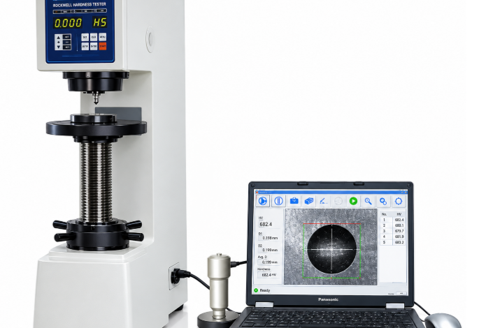
A customer drawing arrives with HBW 10/3000 in the hardness note. Or the plant decides that Brinell checks on castings and forgings will stop going to an outside laboratory. Either way, someone now has to turn a hardness requirement into a machine on a bench.
Before buying a Brinell hardness tester, a lab should check five things against its own work. The machine has to run each ball and force combination the drawings name, hold the force at the specified value and read the impression consistently. The parts have to fit under the indenter and sit firmly on the anvil, and the lab needs a way to verify the machine once it is installed. Maximum force settles only part of the first check.
Bench-mounted Brinell hardness testers press a tungsten carbide ball into the metal under a specified force and hold it there for a set time. Once the load comes off, the diameter of the impression gives the hardness, and a wider mark means a softer metal.
That wide mark is why the method suits castings, forgings and rolled steel plates. On a coarse structure, a small indenter can land on a single grain and return a value that says little about the part. A Brinell impression spans many grains and averages them. The method’s two classic sources of error sit at either end of the test: the force that makes the mark and the reading that measures it.
Each Brinell Scale On The Drawings Has To Be On The Machine
A callout such as HBW 10/3000 has already made the first purchasing decision. It names a 10 mm ball under 3000 kgf, and the hardness value it asks for is tied to that pairing of ball and force. ASTM E10 and ISO 6506 also treat test duration as part of the procedure, so dwell belongs in the requirement too.
Balls of 2.5, 5 and 10 mm are the usual sizes, and each force is specified together with its ball. A dedicated bench machine can carry a long list of these pairs. One current digital design offers the 10 mm ball at six forces from 100 to 3000 kgf and the 5 mm ball at four from 62.5 to 750 kgf. Its 2.5 mm ball runs at 62.5 and 187.5 kgf, and the operator sets dwell on screen for the material, from 1 to 60 seconds.
In that list, 62.5 kgf appears with two different balls. Brinell results are sensitive to both the indenter and the force, so the two count as separate scales.
That makes the scale list the first filter in any comparison. The practical step is to collect the scales in the lab’s drawings and customer specifications, plus the dwell times its procedures call for, and check each against the machine. A pair missing from the machine’s list is a test it cannot run, however much force the frame has in reserve.
Dead Weights Or A Load Cell Behind The Ball
Two machines can list the same scales and still hold the force differently. A classic bench tester builds its test force from dead weights. A closed-loop machine reads the applied force from a load cell and corrects it automatically as the test runs, which is how it holds the specified value.
A digital machine can also run the cycle by itself. It applies the load, holds it for the dwell and releases it, which can improve reproducibility.
Force accuracy can differ across the range. The same digital design states accuracy within 1 percent from 62.5 to 250 kgf and within 0.5 percent from 500 to 3000 kgf. The figure to compare between quotes is the one that covers the lab’s own scale list. For work at HBW 2.5/187.5, that is the 1 percent band, whatever the datasheet states for 3000 kgf.
Eyepiece Or Camera Decides How Much The Operator Matters
The reading is the weaker of the two classic error sources. The hardness number is calculated from the impression diameter, so any error in that diameter passes straight into the result.
Through an eyepiece, the operator judges where the edge of the impression lies, and two people reading the same impression seldom arrive at the same figure. ASTM E10 asks for the average of two diameters measured at right angles to each other, so each result carries two of those judgments.
On that digital machine, a 20X microscope resolves the diameter to 0.005 mm. That figure sets the smallest step the reading can show, while the position of the edge remains the operator’s judgment.
A camera system can take that judgment out of the operator’s hands. On a current system of this kind, a CCD camera captures the impression and a measuring routine finds the diameter at one press of a button. The reading then depends far less on who takes it, and manual measurement stays available for an operator who prefers it.
That system shows the diameters, the hardness value, the tolerance and a pass or fail verdict at the moment of reading. It keeps running statistics and stores each impression image with its report, so a result questioned weeks later can be checked against its image.
Camera reading needs its own calibration. The operator calibrates that system against a standard block by entering either the block’s hardness value or a known indentation diameter. A calibration film comes in the kit. A fair request before ordering is to see that calibration done on blocks at the lab’s own forces, then compare its readings with two operators reading the same impressions.
Heaviest Scale And Largest Part Point To The Right Frame
Laboratories that also run Rockwell, Vickers or Knoop work are choosing from the broader family of metal hardness testers rather than among Brinell machines alone. A universal tester carries the indenters and objectives for several methods on one turret. One frame then does the work of several, which saves bench space and leaves a single calibration record to show an auditor.
Force range divides the work between universal and dedicated frames. On one current universal design, the Brinell scales top out at a 2.5 mm ball under 187.5 kgf, and the 10 mm ball runs at 100 kgf. The dedicated bench machine described earlier takes the 10 mm ball to 3000 kgf. A drawing that calls out HBW 10/3000 points to a dedicated Brinell frame, while lighter Brinell scales run alongside other methods suit a universal one.
The room under the indenter can also change with the method. The same universal design accepts a part up to 220 mm tall for Rockwell but 150 mm for Brinell and Vickers, with 200 mm of horizontal clearance. The dedicated machine has 230 mm of height and 155 mm of depth.
Height decides whether the part fits between anvil and indenter at all, and throat depth decides how far in from an edge the impression can sit. A part that clears the frame for a Rockwell test can still be too tall for a Brinell test on the same machine. The largest part has to be checked against the Brinell figure. Parts too large for any bench frame move the decision to portable Brinell instruments, which ASTM E10 covers when they can meet its verification requirements.
Support matters as much as clearance. A curved or irregular part needs an anvil or fixture that holds it steady and backs the spot under the ball. The most common risk in Brinell work is inconsistent test conditions, and thickness and support sit on that list beside force selection, surface condition and measurement. A part that rocks under the ball changes the test condition, and the reported number can change with it.
Verification Planning Belongs On The Purchase Order
Force range and test space can both check out on a machine that still falls short on verification. The question is whether it supports the verification approach the lab’s quality system relies on and the reporting detail its customers expect. Beyond the test procedure, ASTM E10 covers verification of Brinell testing machines and the standardization of indenters and test blocks. ISO 6506-1 is the test method in a series whose companion parts cover machine verification and calibration, reference block calibration and hardness tables.
Day-to-day verification runs on certified blocks. Hardness testing standards, ASTM among them, call for a block check on each day the tester is used, and again whenever the indenter, the anvil or the test force changes.
Brinell blocks are made and listed for a specific test force, from 62.5 to 3000 kgf. A lab that runs both HBW 10/3000 and HBW 2.5/187.5 therefore needs a block at each force. Each block also has room for a limited number of valid impressions and has to be replaced once its surface is used up.
The blocks carry a traceability chain of their own. When they are calibrated, a load cell and a proving ring can hold the force of the machine making the reference impressions. A calibrated stage micrometer reads them, and all three can be traceable to NIST. Indenters belong in the same plan, since the condition of the ball is one of the machine factors that decide whether results can be used for acceptance testing.
A drawing that cites ASTM E10 without a year leaves one more decision with the lab: which revision governs. That choice belongs in the written procedure, because revisions can change verification wording, reporting expectations and the equipment approaches that are accepted. On the ISO side, many purchase orders name an exact edition, such as ISO 6506-1:2014.
Before a quote is accepted, the supplier’s written answers should cover six points:
- The Brinell scales the machine runs, as ball and force pairs, checked against each scale in the lab’s specifications.
- How the force is applied and held, and the stated accuracy at the forces the lab will use.
- Whether the impression is read through an eyepiece or by camera, and how a camera system is calibrated.
- The test height and throat depth for the Brinell method, and the anvils and supports that suit the parts.
- The certified blocks and indenters supplied, and the forces they cover.
- The edition of ASTM E10 or ISO 6506 the configuration addresses.
A quote that answers all six in writing doubles as the acceptance checklist on installation day.
What Buyers Ask Before Ordering A Brinell Tester
These five questions tend to come up once a purchase moves from catalog pages to a written quote.
- Is A Digital Brinell Hardness Tester The Same As An Automatic One?
Not necessarily. A digital machine can apply, hold and release the load automatically and show the result on a display, while the operator still measures the diameter through a microscope eyepiece. Automatic reading of the impression is a camera-based step that can come built in or be added later as an upgrade. The quote should state which one is included.
- Does ASTM E10 Require A Camera To Measure Brinell Indentations?
No. ASTM E10 and ISO 6506 both recognize manual measurement with a microscope and automatic measurement with CCD-based optical systems. The case for a camera rests on consistency between operators and a stored image of each impression.
- Can An Existing Brinell Tester Be Upgraded With A Camera?
Yes, for the reading step, subject to a fit check. Camera-based measuring scopes exist for manual as well as digital Brinell testers, and they connect to a computer or laptop, so the reading changes while the frame stays. The supplier should confirm the fit against the tester model and the balls and forces in regular use before ordering.
- Can Brinell Hardness Be Converted To Rockwell Or Vickers?
Approximately. Conversion tables such as those in ASTM E140 give an approximate equivalent on another scale, and some measuring software has them built in. Whether a converted value can replace a test on the specified scale is up to the drawing, code or customer requirement that governs the part.
- What Information Does A Supplier Need To Quote A Brinell Tester?
The material, its thickness, the target hardness range and whether testing will happen in the laboratory or in the field give a supplier the basis for a configuration. With the scales in regular use, the largest part and the edition the procedure cites, the supplier can also confirm force range, test space, indenters and blocks before quoting.